Product Overview
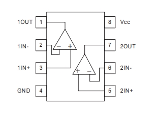
The LM393 Low Offset Voltage Dual Comparator is a high-precision, low-power voltage comparator designed for general-purpose applications. It features two independent voltage comparators that can operate from a single or dual power supply. With low offset voltage, low input bias current, and wide voltage range, the LM393 is ideal for analog signal processing, voltage monitoring, and sensor interfacing. Its open-collector output allows for flexible interfacing with different logic levels and microcontrollers.
Key Features:
- Dual Independent Comparators – Operates as two separate voltage comparators.
- Low Offset Voltage – Ensures high accuracy in signal comparison.
- Wide Supply Voltage Range – Operates from 2V to 36V (single supply) or ±1V to ±18V (dual supply).
- Low Input Bias Current – Reduces power consumption.
- Open-Collector Output – Enables easy interfacing with digital circuits.
- Fast Response Time – Provides quick voltage comparison.
- Low Power Consumption – Ideal for battery-powered applications.
Technical Specifications:
- Model: LM393
- Number of Comparators: 2
- Supply Voltage: 2V to 36V (Single Supply) / ±1V to ±18V (Dual Supply)
- Input Offset Voltage: 5mV (Typical)
- Input Bias Current: 25nA (Typical)
- Response Time: 1.3µs (Typical)
- Output Type: Open Collector
- Power Consumption: 0.4mA (Typical)
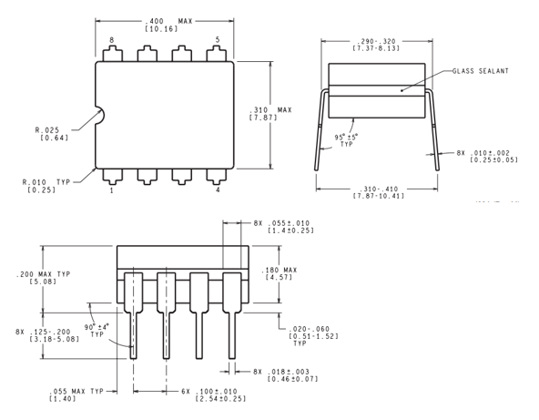
- Package Types: DIP-8, SOIC-8
Applications:
- Voltage Monitoring – Ideal for battery voltage monitoring and power management.
- Sensor Interfacing – Used in temperature, light, and motion sensors.
- Zero-Crossing Detection – Essential for AC signal processing.
- Pulse Width Modulation (PWM) Circuits – Controls motor speed and LED brightness.
- Overvoltage & Undervoltage Protection – Ensures safety in electronic circuits.
Why Choose the LM393?
The LM393 Dual Comparator offers high accuracy, low power consumption, and wide voltage compatibility, making it an excellent choice for engineers and hobbyists in analog and digital circuit design.
Only logged in customers who have purchased this product may leave a review.



Reviews
There are no reviews yet.