
Product Overview
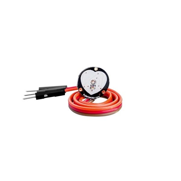
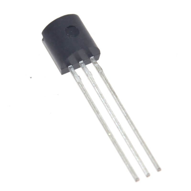
The Heart Rate (Pulse) Sensor is a non-invasive optical sensor designed to measure real-time heart rate through photoplethysmography (PPG). Ideal for wearable health devices, fitness trackers, and medical prototyping, this sensor detects blood flow changes using infrared light, providing accurate pulse data. Compatible with Arduino, Raspberry Pi, and other microcontrollers, it’s perfect for hobbyists, researchers, and developers focused on health tech innovation.
Key Features
- Optical PPG Technology: Infrared LED and photodetector for precise pulse detection.
- Plug-and-Play Integration: Works with 3.3V/5V systems and common platforms (Arduino, ESP32).
- Real-Time Output: Analog/Digital signals for immediate heart rate monitoring.
- Low Power Consumption: 4mA operating current for battery-powered applications.
- Compact Design: Lightweight (15g) and small footprint (20x15mm) for wearables.
- No Soldering Required: Pre-soldered pins for quick prototyping.
- Compliance: CE and RoHS certified for safety.
Technical Specifications
- Measurement Range: 30–250 BPM
- Accuracy: ±2 BPM (resting conditions)
- Response Time: <5 seconds
- Operating Voltage: 3.3V–5V DC
- Output Signal: Analog (0–3.3V) / Digital (TTL)
- LED Wavelength: 940nm (infrared)
- Sampling Rate: 100 Hz
- Interface: I2C, UART (configurable)
- Dimensions: 20mm x 15mm x 5mm
- Operating Temperature: 0°C to 50°C
Benefits
- User-Friendly: Simple wiring and open-source libraries (e.g., Arduino PulseSensor).
- Versatile: Suitable for wearables, lab research, or IoT health monitors.
- Cost-Effective: Affordable alternative to clinical-grade sensors.
- Educational: Ideal for STEM projects on biomedical engineering.
- Durable: Anti-motion artifact design for stable readings during activity.
Usage Instructions
- Wiring: Connect VCC (3.3V/5V), GND, and signal pin to microcontroller.
- Placement: Attach sensor to fingertip or earlobe for optimal blood flow detection.
- Software Setup: Install PulseSensor or similar library; upload sample code.
- Calibration: Rest for 30 seconds to stabilize initial readings.
- Monitoring: View real-time BPM via serial monitor or LCD display.
- Troubleshooting: Ensure minimal ambient light interference for accuracy.
Safety & Storage
- Handling: Avoid bending sensor pins; use gentle pressure on skin contact points.
- Storage: Keep in anti-static bag, away from moisture and direct sunlight.
- Operational Limits: Do not submerge in water or expose to extreme temperatures.
- Medical Disclaimer: Not for diagnostic use; intended for prototyping/education.
Applications
- Fitness trackers and smartwatches
- Patient vital sign monitoring (hospitals, home care)
- Sports science performance analysis
- Stress management devices (biofeedback)
- Biomedical engineering labs and STEM education
- IoT health platforms and telemedicine
Why Choose This Heart Rate Sensor?
Combining accuracy, ease of use, and affordability, this sensor bridges the gap between hobbyist projects and professional health tech development. Its robust design, low power needs, and seamless compatibility with open-source platforms make it a top choice for innovators exploring real-time biometric monitoring. Whether building a fitness gadget or a research tool, this sensor delivers reliable pulse data to bring your ideas to life.
Example Code to Read Heart Rate Sensor Data
Below, you will find an example of how to use a heart rate (pulse) sensor with an Arduino microcontroller. We’ll assume the use of a common pulse sensor, such as the Pulse Sensor Amped, which interfaces via analog output.
Required Components:
- 1 x Arduino board (e.g., Arduino Uno)
- 1 x Heart Rate (Pulse) Sensor (e.g., Pulse Sensor Amped)
- Jumper wires
- Breadboard (optional)
Connection Diagram:
- Sensor VCC: Connect to 5V on Arduino
- Sensor GND: Connect to GND on Arduino
- Sensor Output (SIG): Connect to an analog pin on the Arduino (e.g., A0)
Arduino Code
Here is a simple example code to read the pulse sensor data and display the heart rate on the serial monitor:
// Define the analog input pin for the pulse sensor
const int pulsePin = A0;
// Variables to hold sensor readings
int pulseValue;
int threshold = 512; // Threshold value for detecting heartbeat
int heartRate;
int lastBeatTime = 0; // Last time the sensor detected a beat
int beatCount = 0; // Count of beats detected
void setup() {
Serial.begin(9600); // Start serial communication
pinMode(pulsePin, INPUT); // Set the pulse pin as input
}
void loop() {
pulseValue = analogRead(pulsePin); // Read the pulse sensor value
// Check if pulseValue exceeds the threshold (indicating a heartbeat)
if (pulseValue > threshold) {
// Only count the beat if enough time has elapsed since the last detected beat
if (millis() - lastBeatTime > 1000) { // 1 second debounce
heartRate = beatCount; // Save the current heart rate
beatCount = 0; // Reset the beat count for the next interval
lastBeatTime = millis(); // Update the last beat time
}
beatCount++; // Increment beat count
}
// Output the current heart rate to the serial monitor
if (millis() - lastBeatTime >= 1000) { // Update the heart rate every second
Serial.print("Heart Rate: ");
Serial.print(heartRate);
Serial.println(" BPM");
}
delay(10); // Short delay for stability
}Explanation of the Code:
- Pulse Pin Configuration: The pulse sensor is connected to one of the analog pins (A0) on the Arduino.
- Loop Operation: In the
loop(), the code continuously reads the value from the pulse sensor. - Heartbeat Detection: When the sensor value exceeds a defined threshold (indicating a heartbeat), the code checks whether enough time has passed since the last detected beat to avoid counting noise.
- Heart Rate Calculation: The heart rate is calculated every second, based on the count of detected beats in that period.
- Serial Output: The heart rate in BPM is printed to the serial monitor for monitoring.
Conclusion
This example provides a basic foundation for utilizing a heart rate (pulse) sensor with an Arduino. The code can be tailored for various applications, including fitness tracking, health monitoring, or integration into wearable technology. For best results, make sure to calibrate the threshold and test the sensor under real conditions. Always refer to specific sensor documentation for precise wiring and usage guidelines.
Related products


Reviews
There are no reviews yet.