

In this tutorial, you will learn how to control a stepper motor with the TB6600 microstepping driver and Arduino. This driver is easy to use and can control large stepper motors like a 3 A NEMA 23.
I have included a wiring diagram and 3 example codes. In the first example, I will show you how you can use this stepper motor driver without an Arduino library.
This example can be used to let the motor spin continuously. In the second example, we will look at how you can control the speed, number of revolutions, and spinning direction of the stepper motor.
Finally, we will take a look at the AccelStepper library. This library is fairly easy to use and allows you to add acceleration and deceleration to the movement of the stepper motor.
After each example, I break down and explain how the code works, so you should have no problems modifying it to suit your needs.
If you have any questions, please leave a comment below.
If you would like to learn more about other stepper motor drivers, then the articles below might be useful:
- TB6560 Stepper Motor Driver with Arduino Tutorial
- How to control a stepper motor with A4988 driver and Arduino
- 28BYJ-48 Stepper Motor with ULN2003 Driver and Arduino Tutorial
- How to control a Stepper Motor with Arduino Motor Shield Rev3
Software
Makerguides.com is a participant in the Amazon Services LLC Associates Program, an affiliate advertising program designed to provide a means for sites to earn advertising fees by advertising and linking to products on Amazon.com. As an Amazon Associate we earn from qualifying purchases.
About the driver
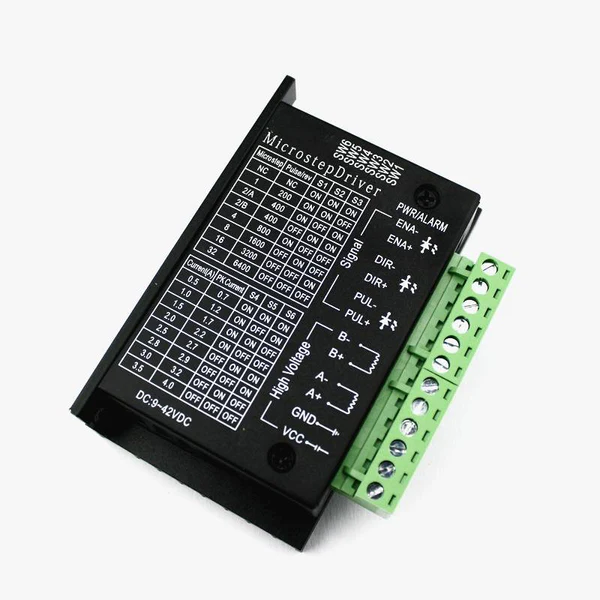
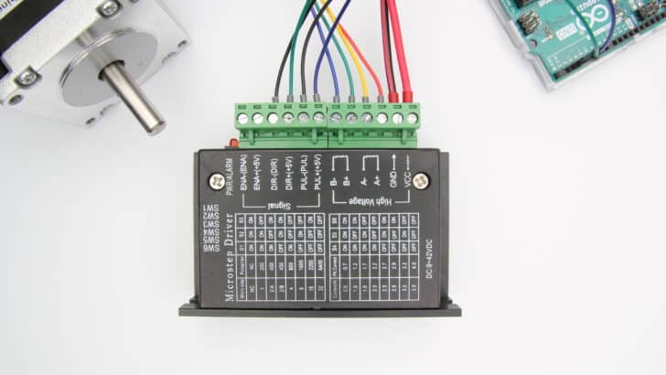
The TB6600 microstepping driver is built around the Toshiba TB6600HG IC and it can be used to drive two-phase bipolar stepper motors.
With a maximum current of 3.5 A continuous, the TB6600 driver can be used to control quite large stepper motors like a NEMA 23. Make sure that you do not connect stepper motors with a current rating of more than 3.5 A to the driver.
The driver has several safety functions built-in like over-current, under-voltage shutdown, and overheating protection.
You can find more specifications in the table below. Note that the exact specifications and dimensions can differ slightly between manufacturers. Always take a look at the datasheet of your particular driver, before connecting power.
TB6600 Specifications
| Operating voltage | 9 – 42 V |
| Max output current | 4.5 A per phase, 5.0 A peak1 |
| Microstep resolution | full, 1/2, 1/4, 1/8 and 1/162 |
| Protection | Low-voltage shutdown, overheating and over-current protection |
| Dimensions | 96 x 72 x 28/36 mm |
| Hole spacing | 88, ⌀ 5 mm |
| Cost | Check price |
1 These are the specifications for the TB6600HG IC, the driver itself has a maximum current rating of 3.5 A and 4.0 A peak.
2 See comment on fake/upgraded TB6600 drivers below.
For more information, you can check out the datasheet and manual below:
Fake or ‘upgraded’ TB6600 drivers
I recently took apart one of the TB6600 drivers I ordered and found out that it didn’t actually use a TB6600HG chip. Instead, it used a much smaller TB67S109AFTG chip, also made by Toshiba. The performance and specifications of these chips are similar, but the TB6600HG does have a higher peak current rating (up to 5 A) and it is just a much larger chip with better heatsinking overall.
There is a very simple way to check if your driver uses a TB6600HG chip or a TB67S109AFTG chip, the TB6600HG only supports up to 1/16 microstepping (see datasheet), whereas the TB67S109AFTG goes to 1/32. The main reason manufacturers switched over to this other chip is probably price. Below you can find links to the chips on LCSC.com which shows that the TB67S109AFTG is around $1.50 cheaper.
TB6600HG: https://lcsc.com/product-detail/Motor-Drivers_TOSHIBA_TB6600HG_TB6600HG_C66042.html
TB67S109AFTG: https://lcsc.com/product-detail/Motor-Drivers_TOSHIBA_TB67S109AFTG_TB67S109AFTG_C92125.html
You can buy genuine TB6600 drivers on Amazon, like this 4-axis driver board but most use the TB67S109AFTG chip. You can tell it uses the TB6600HG chip from the pins sticking out of the PCB and it also only goes up to 1/16 microstepping.
Jim from embeddedtronicsblog did some testing on the TB67S109AFTG drivers and found that the stepper motors ran nicer than with the TB6600 drivers. So should you be going for a genuine TB6600 or the ‘upgrade’? I would say it depends on whether you really need the high current output or if you rather prefer up to 1/32 microstepping.
You can find the datasheet for the TB67S109AFTG below.
Alternatives
Note that the TB6600 is an analog driver. In recent years, digital drivers like the DM556 or DM542 have become much more affordable. Digital drivers usually give much better performance and quieter operation. They can be wired and controlled in the same way as the TB6600, so you can easily upgrade your system later.
I have used the DM556 drivers for my DIY CNC router and they have been working great for several years.
TB6600 vs TB6560
When shopping for a TB6600 stepper motor driver, you will probably come across the slightly cheaper TB6560 driver as well. This driver can be controlled with the same code/wiring, but there are some key differences.
| TB6560 | TB6600 | |
|---|---|---|
| Operating voltage | 10 – 35 VDC, 24 VDC recommended | 9 – 42 VDC, 36 VDC recommended |
| Max output current | 3 A per phase, 3.5 A peak | 3.5 A per phase, 4 A peak |
| # Current settings | 14 | 8 |
| Microstep resolution | full, 1/2, 1/8 and 1/16 | full, 1/2, 1/4, 1/8, 1/16 and 1/32* |
| Clock frequency | 15 kHz | 200 kHz |
| Cost | Check price | Check price |
*Drivers using TB67S109AFTG chip.
So the main differences are the higher maximum voltage, higher maximum current, and up to 1/32 microstepping. The TB6600 also has a better heatsink and a nicer overall form factor. If you want to control larger stepper motors or need a higher resolution, I recommend going with the TB6600.
Wiring – Connecting TB6600 to stepper motor and Arduino
Connecting the TB6600 stepper motor driver to an Arduino and stepper motor is fairly easy. The wiring diagram below shows you which connections you need to make.
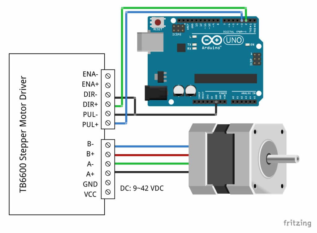
In this tutorial, we will be connecting the driver in a common cathode configuration. This means that we connect all the negative sides of the control signal connections to ground.
The connections are also given in the table below:
TB6600 Connections
| TB6600 | Connection |
|---|---|
| VCC | 9 – 42 VDC |
| GND | Power supply ground |
| ENA- | Not connected |
| ENA+ | Not connected |
| DIR- | Arduino GND |
| DIR+ | Pin 2 Arduino |
| PUL- | Arduino GND |
| PUL+ | Pin 3 Arduino |
| A-, A+ | Coil 1 stepper motor |
| B-, B+ | Coil 2 stepper motor |
Note that we have left the enable pins (ENA- and ENA+) disconnected. This means that the enable pin is always LOW and the driver is always enabled.
How to determine the correct stepper motor wiring?
If you can not find the datasheet of your stepper motor, it can be difficult to figure out which color wire goes where. I use the following trick to determine how to connect 4 wire bipolar stepper motors:
The only thing you need to identify is the two pairs of wires which are connected to the two coils of the motor. The wires from one coil get connected to A- and A+ and the other to B- and B+, the polarity doesn’t matter.
To find the two wires from one coil, do the following with the motor disconnected:
- Try to spin the shaft of the stepper motor by hand and notice how hard it is to turn.
- Now pick a random pair of wires from the motor and touch the bare ends together.
- Next, while holding the ends together, try to spin the shaft of the stepper motor again.
If you feel a lot of resistance, you have found a pair of wires from the same coil. If you can still spin the shaft freely, try another pair of wires. Now connect the two coils to the pins shown in the wiring diagram above.
(If it is still unclear, please leave a comment below, more info can also be found on the RepRap.org wiki)
TB6600 microstep settings
Stepper motors typically have a step size of 1.8° or 200 steps per revolution, this refers to full steps. A microstepping driver such as the TB6600 allows higher resolutions by allowing intermediate step locations. This is achieved by energizing the coils with intermediate current levels.
For instance, driving a motor in 1/2 step mode will give the 200-steps-per-revolution motor 400 microsteps per revolution.
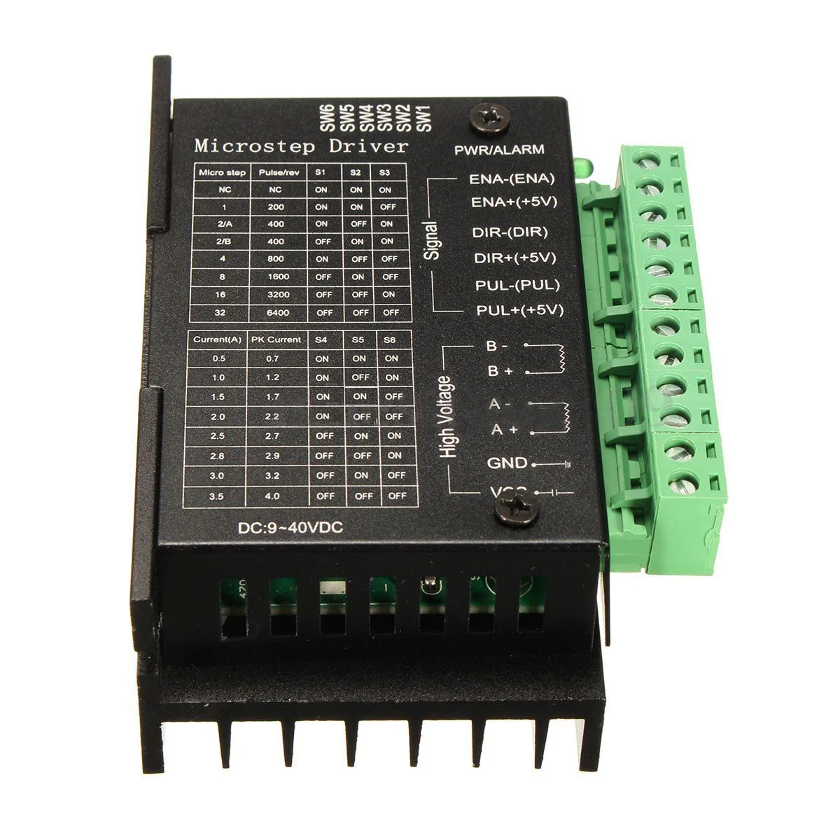
You can change the TB6600 microstep settings by switching the dip switches on the driver on or off. See the table below for details. Make sure that the driver is not connected to power when you adjust the dip switches!
Please note that these settings are for the 1/32 microstepping drivers with the TB67S109AFTG chip. Almost all the TB6600 drivers you can buy nowadays use this chip. Typically you can also find a table with the microstep and current settings on the body of the driver.
Microstep table
| S1 | S2 | S3 | Microstep resolution |
|---|---|---|---|
| ON | ON | ON | NC |
| ON | ON | OFF | Full step |
| ON | OFF | ON | 1/2 step |
| OFF | ON | ON | 1/2 step |
| ON | OFF | OFF | 1/4 step |
| OFF | ON | OFF | 1/8 step |
| OFF | OFF | ON | 1/16 step |
| OFF | OFF | OFF | 1/32 step |
Generally speaking, a smaller microstep setting will result in a smoother and quieter operation. It will however limit the top speed that you can achieve when controlling the stepper motor driver with an Arduino.
TB6600 current settings
You can adjust the current that goes to the motor when it is running by setting the dip switches S4, S5, and S6 on or off. I recommend starting with a current level of 1 A. If your motor is missing steps or stalling, you can always increase the current level later.
Current table
| Current (A) | Peak current | S4 | S5 | S6 |
|---|---|---|---|---|
| 0.5 | 0.7 | ON | ON | ON |
| 1.0 | 1.2 | ON | OFF | ON |
| 1.5 | 1.7 | ON | ON | OFF |
| 2.0 | 2.2 | ON | OFF | OFF |
| 2.5 | 2.7 | OFF | ON | ON |
| 2.8 | 2.9 | OFF | OFF | ON |
| 3.0 | 3.2 | OFF | ON | OFF |
| 3.5 | 4.0 | OFF | OFF | OFF |
Basic TB6600 with Arduino example code
With the following sketch, you can test the functionality of the stepper motor driver. It simply lets the motor rotate at a fixed speed.
You can upload the code to your Arduino using the Arduino IDE. For this specific example, you do not need to install any libraries.
In the next example we will look at controlling the speed, number of revolutions and spinning direction of the stepper motor.
You can copy the code by clicking on the button in the top right corner of the code field.
/* Example sketch to control a stepper motor with TB6600 stepper motor driver
  and Arduino without a library: continuous rotation.
  More info: https://www.makerguides.com */

// Define stepper motor connections:
#define dirPin 2
#define stepPin 3

void setup() {
  // Declare pins as output:
  pinMode(stepPin, OUTPUT);
  pinMode(dirPin, OUTPUT);

  // Set the spinning direction CW/CCW:
  digitalWrite(dirPin, HIGH);
}

void loop() {
  // These four lines result in 1 step:
  digitalWrite(stepPin, HIGH);
  delayMicroseconds(500);
  digitalWrite(stepPin, LOW);
  delayMicroseconds(500);
}
As you can see, the code is very short and super simple. You don’t need much to get a stepper motor spinning!
Code explanation
The sketch starts with defining the step (PUL+) and direction (DIR+) pins. I connected them to Arduino pin 3 and 2.
The statement #define is used to give a name to a constant value. The compiler will replace any references to this constant with the defined value when the program is compiled. So everywhere you mention dirPin, the compiler will replace it with the value 2 when the program is compiled.
</d
Related products