
ريموت كنترول وجويستيك
اسألنا - نرد عليك على واتساب
موديول جويستيك X-Y
☆☆☆☆☆
0.0
(مفيش تقييمات)
رمز المنتج: 30573
50
ج.م
60
وفر 10 ج.م
متوفر
الكمية:
يوصلك خلال 72 ساعة
دفع آمن. نقبل:
بطاقة بنكية
محفظة إلكترونية
الدفع عند الاستلام
إنستا باي
يُشترى معاً عادةً
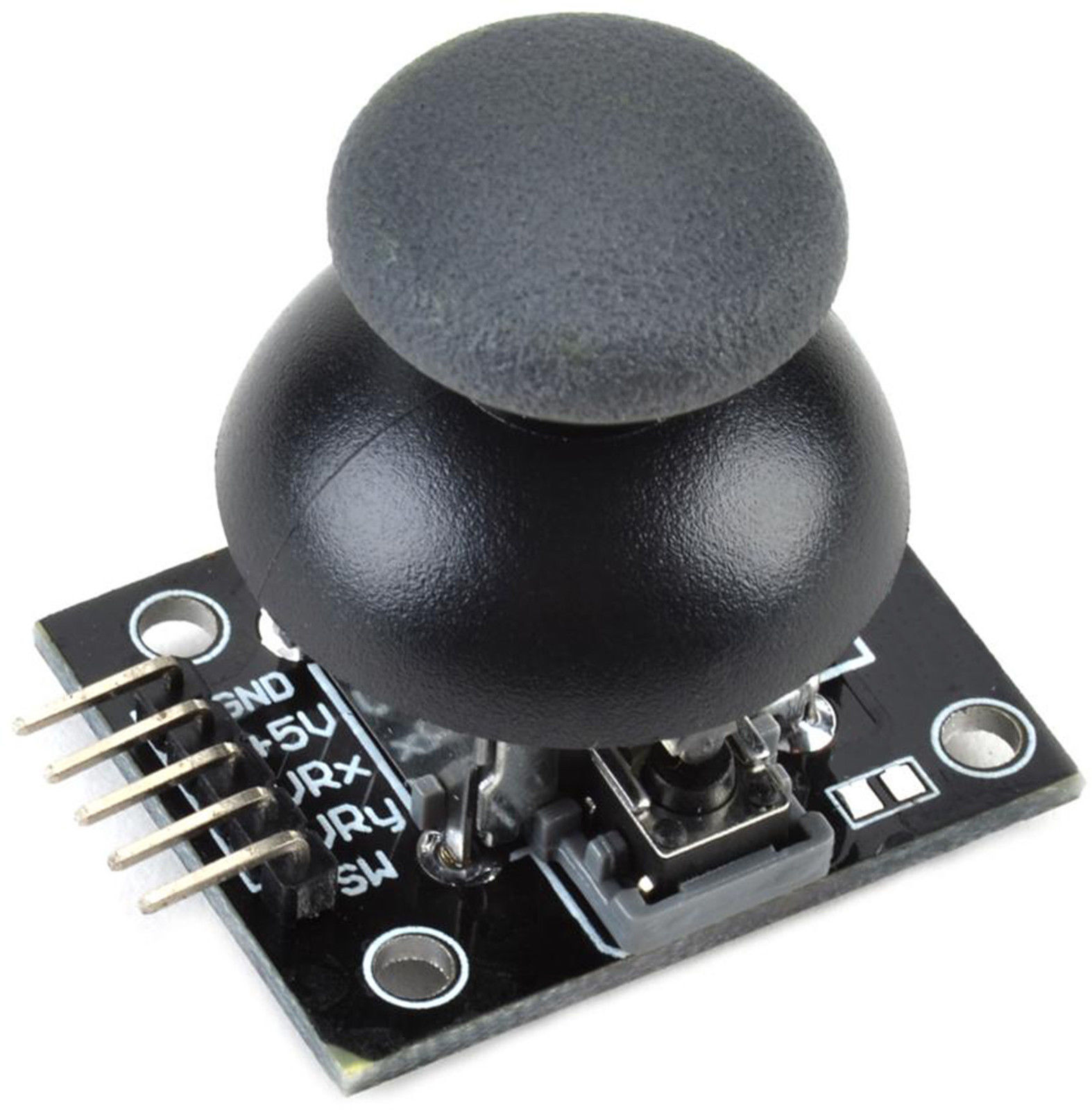 هذا المنتج
موديول جويستيك X-Y
50
ج.م
الإجمالي
137
ج.م
عن هذا المنتج
How 2-Axis Joystick Works & Interface with Arduino + Processing
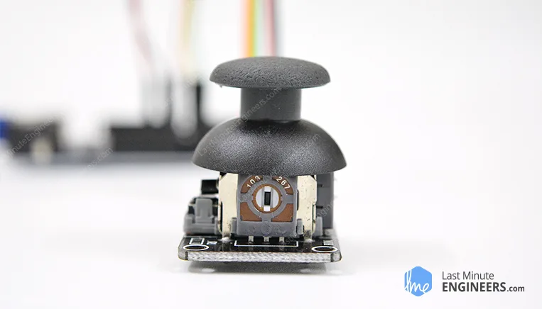
When you hear the word Thumb Joystick, the first thing that comes to mind is the game controllers. They are mainly used for playing games, although in DIY Electronics, there are a lot of fun things you can do with it. Like controlling a robot/a rover, controlling the movement of camera; these are just the tip of the iceberg.
Hardware Overview
This is a joystick very similar to the ‘analog’ joysticks on PS2 (PlayStation 2) controllers. It is a self-centering spring loaded joystick, meaning when you release the joystick it will center itself. It also contains a comfortable cup-type knob/cap which gives the feel of a thumb-stick.
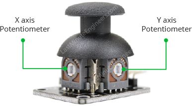
The goal of the joystick is to communicate motion in 2D (2-axis) to an Arduino. This is achieved by housing two independent 10K potentiometers (one per axis). These potentiometers are used as dual adjustable voltage dividers, providing 2-Axis analog input in a control stick form.
The potentiometers are the two blue boxes on the sides of the joystick. If you move the joystick while watching the center shaft of each potentiometer, you’ll see that each of the potentiometers pick up movement in only one direction. We will discuss how they actually work, a little later.
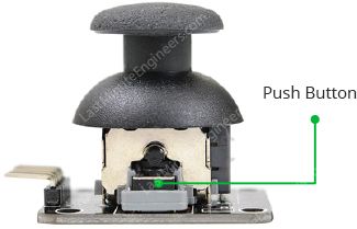
This joystick also contains a switch which activates when you push down on the cap. The switch is the small black box on the rear of the joystick. If you push down on the cap, you can see a lever pushing down on the head of the switch. The lever works no matter what position the joystick is in.
How PS2 2-axis thumb joystick module works?
The basic idea of a joystick is to translate the stick’s position on two axes — the X-axis (left to right) and the Y-axis (up and down) into electronic information an Arduino can process. This can be little tricky, but thanks to the design of the joystick consisting of two potentiometers and a Gimbal Mechanism.
Gimbal Mechanism
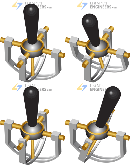
When you rotate the joystick, the thumb handle moves a narrow rod that sits in two rotatable slotted shafts (Gimbal). One of the shafts allows motion in the X-axis (left and right) while the other allows motion in the Y-axis (up and down). Tilting the stick forward and backward pivots the Y-axis shaft from side to side. Tilting it left to right pivots the X-axis shaft. When you move the stick diagonally, it pivots both shafts.
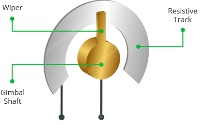
A potentiometer is connected to each joystick shaft that interprets the position of the rod as analog readings. Moving the slotted shafts rotates the contact arm of the potentiometer. In other words, if you push the stick all the way forward, it will turn the potentiometer contact arm to one end of the track, and if you pull it back toward you, it will turn the contact arm the other way.
Reading analog values from Joystick
In order to read the joystick’s physical position, we need to measure the change in resistance of a potentiometer. This change can be read by an Arduino analog pin using ADC.
As the Arduino board has an ADC resolution of 10 bits, the values on each analog channel (axis) can vary from 0 to 1023. So, if the stick is moved on X axis from one end to the other, the X values will change from 0 to 1023 and similar thing happens when moved along the Y axis. When the joystick stays in its center position the value is around 512.
The graphic below shows the X and Y directions and also gives an indication of how the outputs will respond when the joystick is pushed in various directions.
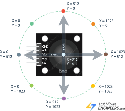
In order to put this thumb joystick to use, you are going to want to understand which direction is X and which direction is Y. You will also need to decipher the direction it is being pushed in either the X or the Y direction.
Thumb Joystick Module Pinout
Let’s have a look at the pinout of PS2 2-axis Thumb Joystick module.
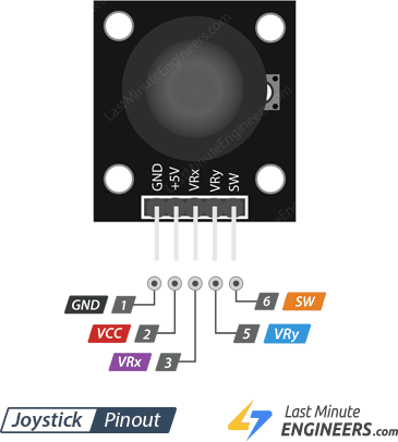
GND is the Ground Pin which we connect the GND pin on the Arduino.
VCC supplies power for the module. You can connect it to 5V output from your Arduino.
VRx gives readout of the joystick in the horizontal direction (X-coordinate) i.e. how far left and right the joystick is pushed.
VRy gives readout of the joystick in the vertical direction (Y-coordinate) i.e. how far up and down the joystick is pushed.
SW is the output from the pushbutton. It’s normally open, meaning the digital readout from the SW pin will be HIGH. When the button is pushed, it will connect to GND, giving output LOW.
Wiring – Connecting Thumb Joystick Module to Arduino UNO
Now that we know everything about the module it is time to put them to use!
As we know, in order to determine the X and Y coordinates of the joystick, we need to connect both analog outputs from the joystick to analog pins on the Arduino. For our Arduino board, we connect VRx to analog pin A0 of the Arduino and VRy to analog pin A1 of the Arduino.
To read whether the joystick knob has been pressed down, we connect the SW pin of the joystick to digital pin D8 of the Arduino.
Other than this, the joystick just simply needs power. Its VCC pin is connected to the 5V terminal of the Arduino and its GND pin is connected to the GND terminal of the Arduino.
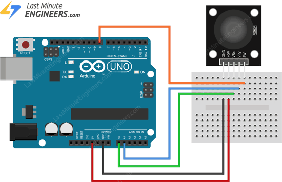 Wiring PS2 2-axis Joystick Module with Arduino UNO
That’s it. Now you are ready to show your Joystick manipulation skills.
Arduino Code
The program is very simple. We will read the measurement from two analog inputs and one digital input. Then we will display the result on serial monitor.
// Arduino pin numbers
constint SW_pin = 8; // digital pin connected to switch output
constint X_pin = 0; // analog pin connected to X output
constint Y_pin = 1; // analog pin connected to Y output
voidsetup() {
pinMode(SW_pin, INPUT);
digitalWrite(SW_pin, HIGH);
Serial.begin(9600);
}
voidloop() {
Serial.print("Switch: ");
Serial.print(digitalRead(SW_pin));
Serial.print(" | ");
Serial.print("X-axis: ");
Serial.print(analogRead(X_pin));
Serial.print(" | ");
Serial.print("Y-axis: ");
Serial.print(analogRead(Y_pin));
Serial.println(" | ");
delay(200);
}
If everything is fine, you should see below output on serial monitor.
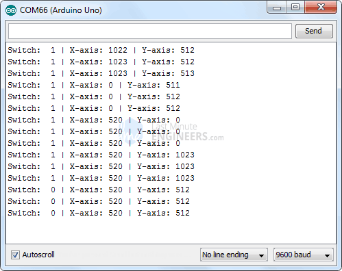 Joystick Module Output On Serial Monitor
Code Explanation:
The sketch starts by initializing connections of Joystick module on the Arduino. The SW pin is connected to Arduino Pin#8 while the VRx and VRy pins are connected to Analog pin #0 and #1.
// Arduino pin numbers
constint SW_pin = 8; // digital pin connected to switch output
constint X_pin = 0; // analog pin connected to X output
constint Y_pin = 1; // analog pin connected to Y output
In setup() function: We initialize the SW pin as an input and keep it HIGH. This is because as long as the SW pin is HIGH, we know that the button is not pressed. We also start the serial communication.
pinMode(SW_pin, INPUT);
digitalWrite(SW_pin, HIGH);
Serial.begin(9600);
In loop() function: We merely read the value of SW pin using digitalRead() function, VRx & VRy pin using analogRead() and display on serial monitor.
Serial.print("Switch: ");
Serial.print(digitalRead(SW_pin));
Serial.print(" | ");
Serial.print("X-axis: ");
Serial.print(analogRead(X_pin));
Serial.print(" | ");
Serial.print("Y-axis: ");
Serial.print(analogRead(Y_pin));
Serial.println(" | ");
delay(200);
Animating Joystick Movements In Processing IDE
Let’s create a quick Arduino project to demonstrate how a simple 2-Axis Joystick module can be used for controlling animations in Processing IDE. First we will program our Arduino to spit values of x-axis, y-axis and button state on serial port. We will receive these values coming from serial port in Processing IDE. These values can then be used to animate joystick position. Great! Right?
This is how the output looks like.
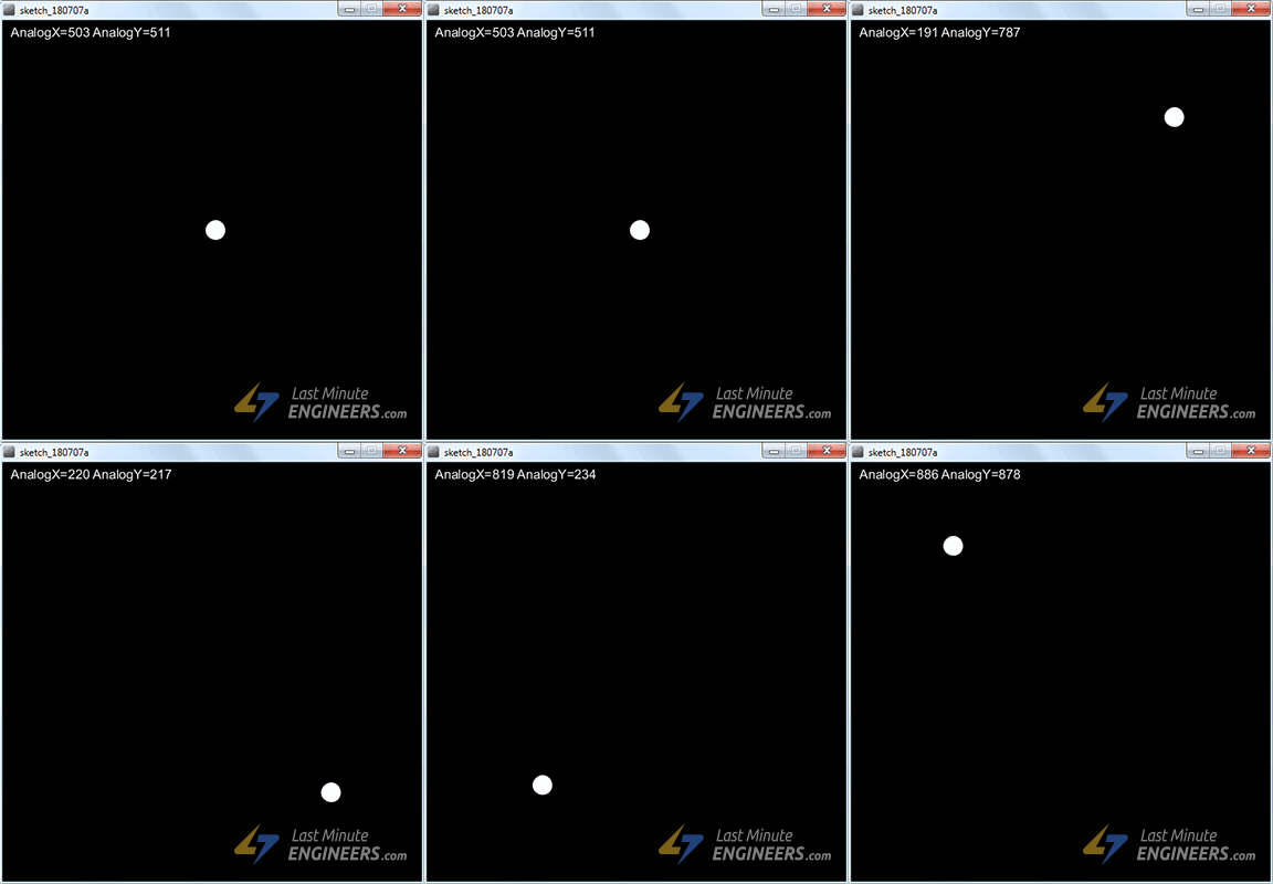 Joystick movement animation in Precessing IDE
Of course this project could be extended to animate characters, surveillance projects or controlling unmanned vehicles.
Arduino Code
To start with, we need to program our Arduino to spit values of x-axis, y-axis and button state on serial port. The program is quite same as above except the values we print on serial monitor are comma-separated. Why comma-separated? Because this is a popular format for transferring data from one application to another. In Processing IDE we can split incoming values by ‘comma’ character and get our data back.
Upload following sketch to your Arduino.
int xValue = 0 ; // read value of the X axis
int yValue = 0 ; // read value of the Y axis
int bValue = 0 ; // value of the button reading
voidsetup()
{
Serial.begin(9600) ; // Open the serial port
pinMode(8,INPUT) ; // Configure Pin 2 as input
digitalWrite(8,HIGH);
}
voidloop()
{
// Read analog port values A0 and A1
xValue = analogRead(A0);
yValue = analogRead(A1);
// Read the logic value on pin 2
bValue = digitalRead(8);
// We display our data separated by a comma
Serial.print(xValue,DEC);
Serial.print(",");
Serial.print(yValue,DEC);
Serial.print(",");
Serial.print(!bValue);
// We end with a newline character to facilitate subsequent analysis
Serial.print("\
");
// Small delay before the next measurement
delay(10);
}
Processing Code
Once the program is uploaded to Arduino, we can start animating Joystick position in Processing IDE. Keep your Arduino plugged and Run following Processing code.
import processing.serial.*; //import the Serial library
Serial myPort;
int x; // variable holding the value from A0
int y; // variable holding the value from A1
int b; // variable holding the value from digital pin 2
PFont f; // define the font variable
String portName;
String val;
voidsetup()
{
size ( 512 , 512 ) ; // window size
// we are opening the port
myPort = new Serial(this, Serial.list(), 9600);
myPort.bufferUntil('\
');
// choose the font and size
f = createFont("Arial", 16, true); // Arial, 16px, anti-aliasing
textFont ( f, 16 ) ; // size 16px
}
// drawing loop
voiddraw()
{
fill(0) ; // set the fill color to black
clear() ; // clean the screen
fill(255) ; // set the fill color to white
if (b == 1) // check if the button is pressed
{
// draw a larger circle with specified coordinates
ellipse(x/2,y/2, 50, 50);
}
else
{
// we draw a circle with a certain coordinates
ellipse(x/2,y/2, 25, 25);
}
// we display data
text("AnalogX="+(1023-x)+" AnalogY="+(1023-y),10,20);
}
// data support from the serial port
المواصفات التقنية
لسه مفيش مواصفات مسجلة
بنسجل المواصفات التقنية للمنتج ده وهتظهر هنا أول ما تخلص.
التقييمات
0.0
☆☆☆☆☆
لسه مفيش تقييمات
5★
0
4★
0
3★
0
2★
0
1★
0
لسه مفيش تقييمات للمنتج ده
كن أول واحد يقيّمه وتساعد اللي بعدك يقرر.
الأسئلة الشائعة
لسه مفيش أسئلة على المنتج ده
أول ما توصلنا أسئلة متكررة على المنتج ده هنجاوب عليها هنا.
مش لاقي إجابتك؟
اسألنا - نرد عليك على واتساب
منتجات مرتبطة
قد يعجبك أيضاً
 متوفر
متوفر
ريموت كنترول وجويستيك
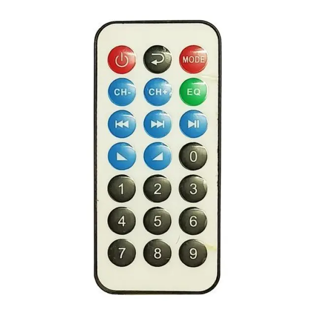
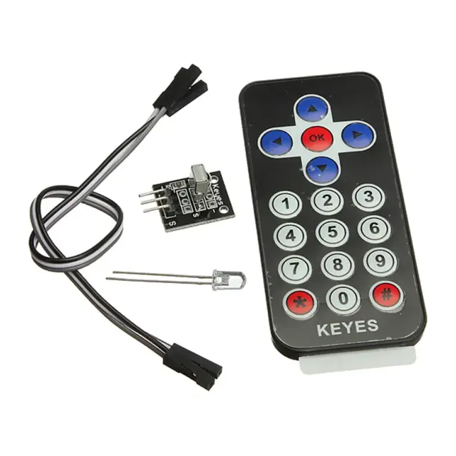
ريموت تحكم رحمة تك بالأشعة تحت الحمراء للتحكم في الصوت والتشغيل مع بطارية
★★★★★
(0)
20
ج.م
 متوفر
متوفر
 متوفر
متوفر
 متاح للطلب
 متاح للطلب
 متوفر
متوفر
روبوتات وريموت كنترول
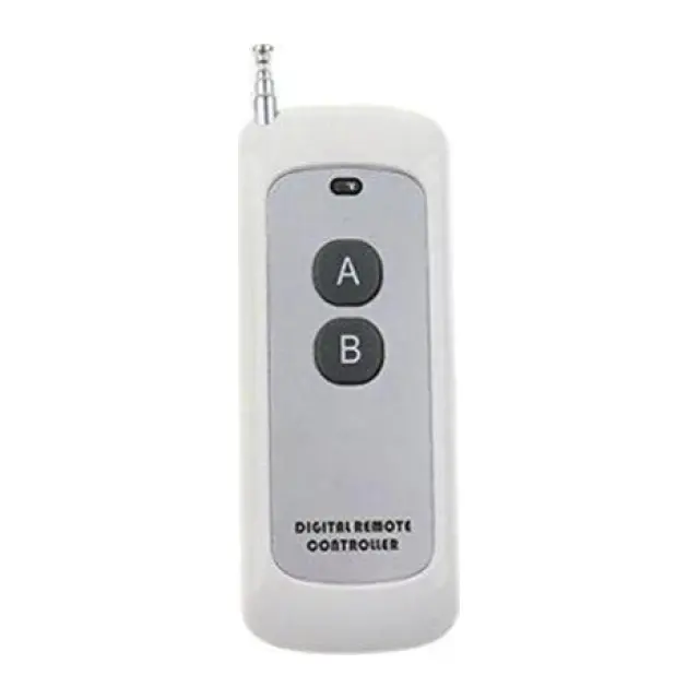
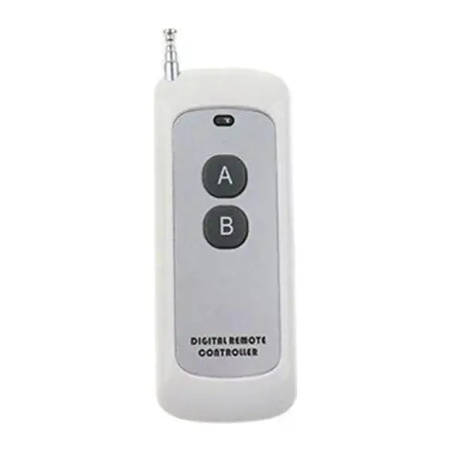
ريموت كنترول RF لاسلكي 433 ميجاهرتز مدى 1000 متر 2 قناة مع حامل
★★★★★
(0)
350
ج.م
 متوفر
متوفر
 متاح للطلب
50
ج.م
60
متوفر - يوصلك خلال 72 ساعة