
قطع إلكترونية
اسألنا - نرد عليك على واتساب
موديول سنسور معدل ضربات القلب MAX30100 - أخضر
☆☆☆☆☆
0.0
(مفيش تقييمات)
رمز المنتج: 36192
100
ج.م
متوفر
الكمية:
يوصلك خلال 72 ساعة
دفع آمن. نقبل:
بطاقة بنكية
محفظة إلكترونية
الدفع عند الاستلام
إنستا باي
يُشترى معاً عادةً
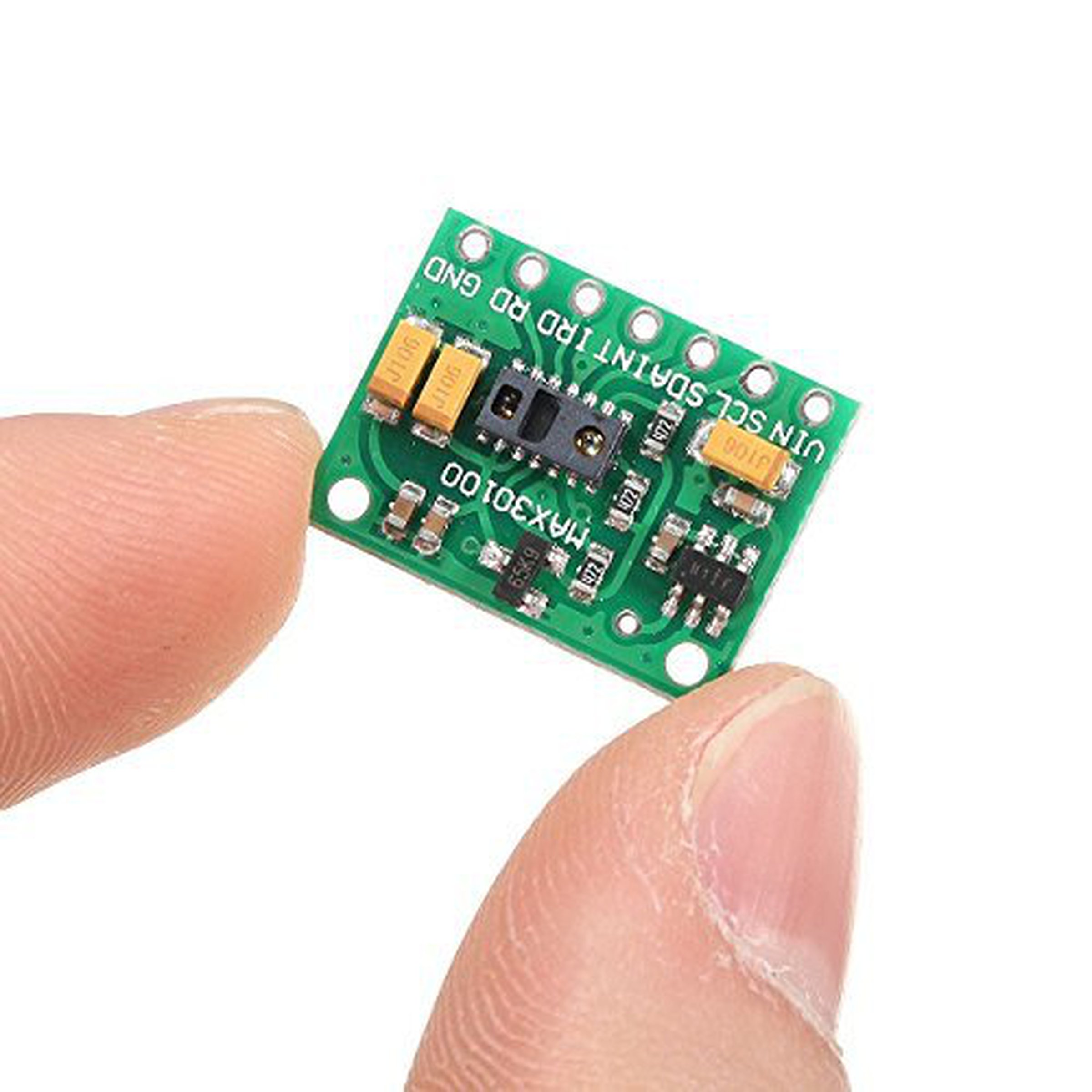 هذا المنتج
موديول سنسور معدل ضربات القلب MAX30100 - أخضر
100
ج.م
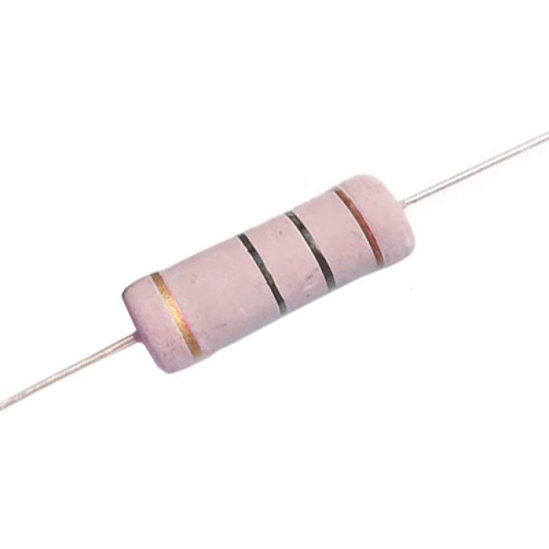
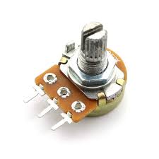
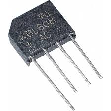
الإجمالي
114
ج.م
عن هذا المنتج
The MAX30100 pulse oximeter and heart rate sensor is an I2C-based low-power plug-and-play biometric sensor. It can be used by students, hobbyists, engineers, manufacturers, and game & mobile developers who want to incorporate live heart-rate data into their projects.
The module features the MAX30100 – a modern, integrated pulse oximeter and heart rate sensor IC, from Analog Devices. It combines two LEDs, a photodetector, optimized optics, and low-noise analog signal processing to detect pulse oximetry (SpO2) and heart rate (HR) signals.
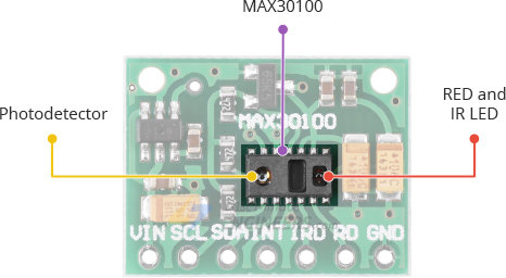
On the right, the MAX30100 has two LEDs – a RED and an IR LED. And on the left is a very sensitive photodetector. The idea is that you shine a single LED at a time, detecting the amount of light shining back at the detector, and, based on the signature, you can measure blood oxygen level and heart rate.
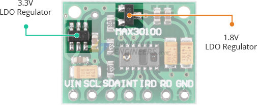
The MAX30100 chip requires two different supply voltages: 1.8V for the IC and 3.3V for the RED and IR LEDs. So the module comes with 3.3V and 1.8V regulators. This allows you to connect the module to any microcontroller with 5V, 3.3V, even 1.8V level I/O.
One of the most important features of the MAX30100 is its low power consumption: the MAX30100 consumes less than 600μA during measurement. Also it is possible to put the MAX30100 in standby mode, where it consumes only 0.7μA. This low power consumption allows implementation in battery powered devices such as handsets, wearables or smart watches.
The MAX30100 has an on-chip temperature sensor that can be used to compensate for the changes in the environment and to calibrate the measurements.
This is a reasonably precise temperature sensor that measures the ‘die temperature’ in the range of -40˚C to +85˚C with an accuracy of ±1˚C.
The module uses a simple two-wire I2C interface for communication with the microcontroller. It has a fixed I2C address: 0xAEHEX (for write operation) and 0xAFHEX (for read operation).
The MAX30100 embeds a FIFO buffer for storing data samples. The FIFO has a 16-sample memory bank, which means it can hold up to 16 SpO2 and heart rate samples. The FIFO buffer can offload the microcontroller from reading each new data sample from the sensor, thereby saving system power.
The MAX30100 can be programmed to generate an interrupt, allowing the host microcontroller to perform other tasks while the data is collected by the sensor. The interrupt can be enabled for 5 different sources:
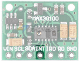
The INT line is an open-drain, so it is pulled HIGH by the onboard resistor. When an interrupt occurs the INT pin goes LOW and stays LOW until the interrupt is cleared.
Here are the technical specifications:
You can find extensive information for the MAX30100 sensor from the datasheet.
MAX30100 vs. MAX30102
Analog Devices has stepped up their game with their new MAX30102 sensor. The MAX30102 beats the MAX30100 in these areas:
FIFO – The MAX30102 has a 32-sample memory bank, which means it can hold up to 32 SpO2 and heart rate samples. Whereas only 16 samples can be kept in MAX30100.
ADC Resolution – The MAX30102 is capable of reading up to 18-bits or values up to 262,144. Whereas the MAX30100 only has 16-bit ADC resolution. Because of that the MAX30102 can detect extremely small movements.
LED Pulse Width – The MAX30102 has a narrower LED pulse width than the MAX30100, resulting in lower power consumption.
To get started with the MAX30102 module, you can refer to the tutorial below
The MAX30100, or any optical pulse oximeter and heart-rate sensor for that matter, consists of a pair of high-intensity LEDs (RED and IR, both of different wavelengths) and a photodetector. The wavelengths of these LEDs are 660nm and 880nm, respectively.
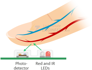
The MAX30100 works by shining both lights onto the finger or earlobe (or essentially anywhere where the skin isn’t too thick, so both lights can easily penetrate the tissue) and measuring the amount of reflected light using a photodetector. This method of pulse detection through light is called Photoplethysmogram.
The working of MAX30100 can be divided into two parts: Heart Rate Measurement and Pulse Oximetry (measuring the oxygen level of the blood).
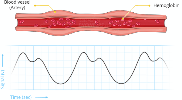
The oxygenated hemoglobin (HbO2) in the arterial blood has the characteristic of absorbing IR light. The redder the blood (the higher the hemoglobin), the more IR light is absorbed. As the blood is pumped through the finger with each heartbeat, the amount of reflected light changes, creating a changing waveform at the output of the photodetector. As you continue to shine light and take photodetector readings, you quickly start to get a heart-beat (HR) pulse reading.
Pulse oximetry is based on the principle that the amount of RED and IR light absorbed varies depending on the amount of oxygen in your blood. The following graph is the absorption-spectrum of oxygenated hemoglobin (HbO2) and deoxygenated hemoglobin (Hb).
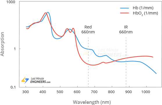
As you can see from the graph, deoxygenated blood absorbs more RED light (660nm), while oxygenated blood absorbs more IR light (880nm). By measuring the ratio of IR and RED light received by the photodetector, the oxygen level (SpO2) in the blood is calculated.
Did you know?
The measurement of hemoglobin oxygen saturation (HbO2) by measuring the absorbance of red and IR light was introduced in 1935 by a German physician, Karl Matthes.
At first, there were no good photodetectors so instead of the IR band, the green band of the light spectrum was used. As technology advanced, more reliable methods were developed, and green light was replaced by IR light.
The MAX30100 module brings out the following connections.
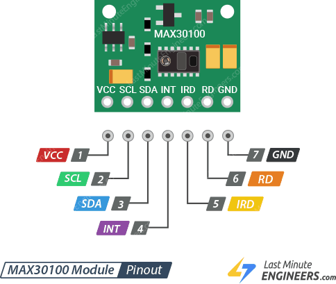
VIN is the power pin. You can connect it to 3.3V or 5V output from your Arduino.
SCL is the I2C clock pin, connect to your Arduino’s I2C clock line.
SDA is the I2C data pin, connect to your Arduino’s I2C data line.
INT The MAX30100 can be programmed to generate an interrupt for each pulse. This line is open-drain, so it is pulled HIGH by the onboard resistor. When an interrupt occurs the INT pin goes LOW and stays LOW until the interrupt is cleared.
IRD The MAX30100 integrates an LED driver to drive LED pulses for SpO2 and HR measurements. Use this if you want to drive the IR LED yourself, otherwise leave it unconnected.
RD pin is similar to the IRD pin, but is used to drive the Red LED. If you don’t want to drive the red LED yourself, leave it unconnected.
GND is the ground.
There is no doubt that the MAX30100 module is cheap and very popular among hobbyists, but unfortunately the module (sold in the thousands) has a serious design problem. Well, let’s fix it.
The MAX30100 chip requires two different supply voltages: 1.8V for the IC and 3.3V for the RED and IR LEDs. So the module comes with two linear voltage regulators – U1 and U2. The first generates 5V to 3.3V. The second regulator is connected to the output of the first and generates 1.8V.
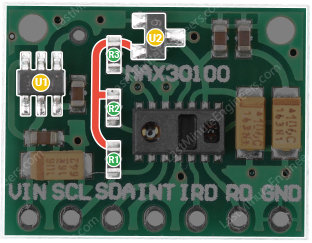
Now take a closer look at the 4.7kΩ pull-up resistors (R1, R2 and R3) for the SCL, SDA and INT signal lines. They are connected to the 1.8V supply (highlighted with a thick red line)!
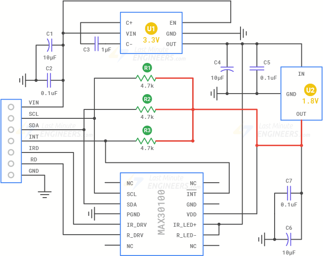
The two regulators U1, U2 and the trace that connects the 4.7kΩ pull-up resistors to the 1.8V supply are highlighted on the module as well.
If you connect such module to the Arduino’s 5V logic – it will not show up on the I2C bus because the logic level is too low (Arduino reports HIGH if the voltage exceeds 3.0V for 5V-boards and 2.0V for 3.3V-boards). Even with a 3.3V logic board, it will not work.
Don’t worry! We have two solutions to fix this problem.
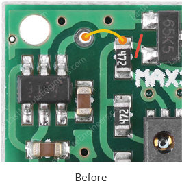
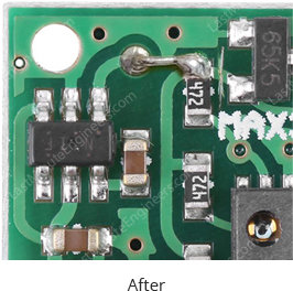
Here’s the board with and without the modifications:
After following these steps, connect the module to the Arduino UNO using the wiring diagram below:
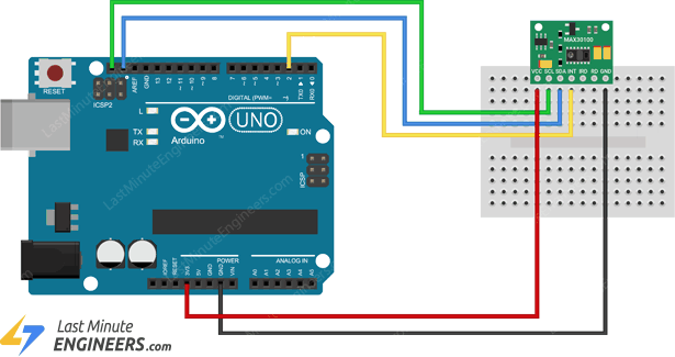
The wiring is fairly easy. Simply connect the VIN pin to Arduino’s 3.3V and GND to ground. Connect the SCL pin to the I2C clock pin and the SDA pin to the I2C data pin on your Arduino. Finally connect the INT pin to digital pin 2.
The second solution is to remove all 4.7kΩ pullup resistors from the board. We will use external pullup resistors on the SCL, SDA and INT signal lines later.
Here’s the board with and without the resistors removed:
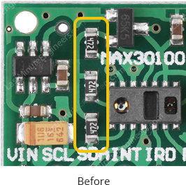
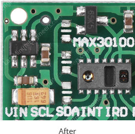
After removing the resistors, connect the module to the Arduino UNO using the wiring diagram below:
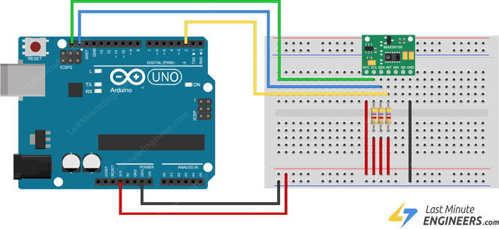
The wiring is the same as the first one; you just need to add external 4.7kΩ pullup resistors on the SCL, SDA and INT signal lines.
We have tested both solutions and they work great. So try one which is easier for you to implement.
There are several libraries available for the MAX30100 sensor. However in our example, we are using the one by OXullo Intersecans. This library exposes most of the features of the MAX30100 and offers simple and easy to use functions to calculate pulse rate and SpO2. You can download this library from within the Arduino IDE Library Manager.
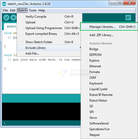
To install the library navigate to the Sketch > Include Library > Manage Libraries… Wait for Library Manager to download libraries index and update list of installed libraries.
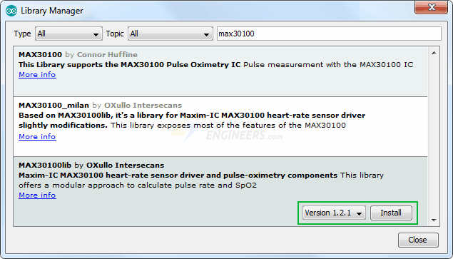
Filter your search by typing max30100. There should be a couple entries. Look for MAX30100lib Library by OXullo Intersecans. Click on the entry, and then select Install.
This is where the fun really begins! In this example, we’ll measure heart rate (Beats Per Minute or BPM) and blood oxygen level (SpO2) of the person we’re monitoring.
Warning:
This sketch detects heart-rate and oxygen saturation optically. This method is tricky and prone to give false readings. So please DO NOT use it for actual medical diagnosis.
#include
#include "MAX30100_PulseOximeter.h"
#define REPORTING_PERIOD_MS 1000
// Create a PulseOximeter object
PulseOximeter pox;
// Time at which the last beat occurred
uint32_t tsLastReport = 0;
// Callback routine is executed when a pulse is detected
voidonBeatDetected() {
Serial.println("Beat!");
}
voidsetup() {
Serial.begin(9600);
Serial.print("Initializing pulse oximeter..");
// Initialize sensor
if (!pox.begin()) {
Serial.println("FAILED");
for(;;);
} else {
Serial.println("SUCCESS");
}
// Configure sensor to use 7.6mA for LED drive
pox.setIRLedCurrent(MAX30100_LED_CURR_7_6MA);
// Register a callback routine
pox.setOnBeatDetectedCallback(onBeatDetected)
MAX30100 Module Hardware Overview
The module features the MAX30100 – a modern, integrated pulse oximeter and heart rate sensor IC, from Analog Devices. It combines two LEDs, a photodetector, optimized optics, and low-noise analog signal processing to detect pulse oximetry (SpO2) and heart rate (HR) signals.
On the right, the MAX30100 has two LEDs – a RED and an IR LED. And on the left is a very sensitive photodetector. The idea is that you shine a single LED at a time, detecting the amount of light shining back at the detector, and, based on the signature, you can measure blood oxygen level and heart rate.
Power Requirement
The MAX30100 chip requires two different supply voltages: 1.8V for the IC and 3.3V for the RED and IR LEDs. So the module comes with 3.3V and 1.8V regulators. This allows you to connect the module to any microcontroller with 5V, 3.3V, even 1.8V level I/O.
One of the most important features of the MAX30100 is its low power consumption: the MAX30100 consumes less than 600μA during measurement. Also it is possible to put the MAX30100 in standby mode, where it consumes only 0.7μA. This low power consumption allows implementation in battery powered devices such as handsets, wearables or smart watches.
On-Chip Temperature Sensor
The MAX30100 has an on-chip temperature sensor that can be used to compensate for the changes in the environment and to calibrate the measurements.
This is a reasonably precise temperature sensor that measures the ‘die temperature’ in the range of -40˚C to +85˚C with an accuracy of ±1˚C.
I2C Interface
The module uses a simple two-wire I2C interface for communication with the microcontroller. It has a fixed I2C address: 0xAEHEX (for write operation) and 0xAFHEX (for read operation).
FIFO Buffer
The MAX30100 embeds a FIFO buffer for storing data samples. The FIFO has a 16-sample memory bank, which means it can hold up to 16 SpO2 and heart rate samples. The FIFO buffer can offload the microcontroller from reading each new data sample from the sensor, thereby saving system power.
Interrupts
The MAX30100 can be programmed to generate an interrupt, allowing the host microcontroller to perform other tasks while the data is collected by the sensor. The interrupt can be enabled for 5 different sources:
- Power Ready : triggers on power-up or after a brownout condition.
- SpO2 Data Ready : triggers after every SpO2 data sample is collected.
- Heart Rate Data Ready : triggers after every heart rate data sample is collected.
- Temperature Ready : triggers when an internal die temperature conversion is finished.
- FIFO Almost Full : triggers when the FIFO becomes full and future data is about to lost.
The INT line is an open-drain, so it is pulled HIGH by the onboard resistor. When an interrupt occurs the INT pin goes LOW and stays LOW until the interrupt is cleared.
Technical Specifications
Here are the technical specifications:
| Power supply | 3.3V to 5.5V |
| Current draw | ~600μA (during measurements) |
| ~0.7μA (during standby mode) | |
| Red LED Wavelength | 660nm |
| IR LED Wavelength | 880nm |
| Temperature Range | -40˚C to +85˚C |
| Temperature Accuracy | ±1˚C |
You can find extensive information for the MAX30100 sensor from the datasheet.
MAX30100 vs. MAX30102
Analog Devices has stepped up their game with their new MAX30102 sensor. The MAX30102 beats the MAX30100 in these areas:
FIFO – The MAX30102 has a 32-sample memory bank, which means it can hold up to 32 SpO2 and heart rate samples. Whereas only 16 samples can be kept in MAX30100.
ADC Resolution – The MAX30102 is capable of reading up to 18-bits or values up to 262,144. Whereas the MAX30100 only has 16-bit ADC resolution. Because of that the MAX30102 can detect extremely small movements.
LED Pulse Width – The MAX30102 has a narrower LED pulse width than the MAX30100, resulting in lower power consumption.
To get started with the MAX30102 module, you can refer to the tutorial below
Interfacing MAX30102 Pulse Oximeter and Heart Rate Sensor with Arduino
The MAX30102 pulse oximeter and heart rate sensor is an I2C-based low-power plug-and-play biometric sensor. It can be used by students, hobbyists, engineers, manufacturers, and…
How MAX30100 Pulse Oximeter and Heart Rate Sensor Works?
The MAX30100, or any optical pulse oximeter and heart-rate sensor for that matter, consists of a pair of high-intensity LEDs (RED and IR, both of different wavelengths) and a photodetector. The wavelengths of these LEDs are 660nm and 880nm, respectively.
The MAX30100 works by shining both lights onto the finger or earlobe (or essentially anywhere where the skin isn’t too thick, so both lights can easily penetrate the tissue) and measuring the amount of reflected light using a photodetector. This method of pulse detection through light is called Photoplethysmogram.
The working of MAX30100 can be divided into two parts: Heart Rate Measurement and Pulse Oximetry (measuring the oxygen level of the blood).
Heart Rate Measurement
The oxygenated hemoglobin (HbO2) in the arterial blood has the characteristic of absorbing IR light. The redder the blood (the higher the hemoglobin), the more IR light is absorbed. As the blood is pumped through the finger with each heartbeat, the amount of reflected light changes, creating a changing waveform at the output of the photodetector. As you continue to shine light and take photodetector readings, you quickly start to get a heart-beat (HR) pulse reading.
Pulse Oximetry
Pulse oximetry is based on the principle that the amount of RED and IR light absorbed varies depending on the amount of oxygen in your blood. The following graph is the absorption-spectrum of oxygenated hemoglobin (HbO2) and deoxygenated hemoglobin (Hb).
As you can see from the graph, deoxygenated blood absorbs more RED light (660nm), while oxygenated blood absorbs more IR light (880nm). By measuring the ratio of IR and RED light received by the photodetector, the oxygen level (SpO2) in the blood is calculated.
Did you know?
The measurement of hemoglobin oxygen saturation (HbO2) by measuring the absorbance of red and IR light was introduced in 1935 by a German physician, Karl Matthes.
At first, there were no good photodetectors so instead of the IR band, the green band of the light spectrum was used. As technology advanced, more reliable methods were developed, and green light was replaced by IR light.
MAX30100 Module Pinout
The MAX30100 module brings out the following connections.
VIN is the power pin. You can connect it to 3.3V or 5V output from your Arduino.
SCL is the I2C clock pin, connect to your Arduino’s I2C clock line.
SDA is the I2C data pin, connect to your Arduino’s I2C data line.
INT The MAX30100 can be programmed to generate an interrupt for each pulse. This line is open-drain, so it is pulled HIGH by the onboard resistor. When an interrupt occurs the INT pin goes LOW and stays LOW until the interrupt is cleared.
IRD The MAX30100 integrates an LED driver to drive LED pulses for SpO2 and HR measurements. Use this if you want to drive the IR LED yourself, otherwise leave it unconnected.
RD pin is similar to the IRD pin, but is used to drive the Red LED. If you don’t want to drive the red LED yourself, leave it unconnected.
GND is the ground.
MAX30100 Not Working – Problem and Solutions to Fix
There is no doubt that the MAX30100 module is cheap and very popular among hobbyists, but unfortunately the module (sold in the thousands) has a serious design problem. Well, let’s fix it.
The Problem
The MAX30100 chip requires two different supply voltages: 1.8V for the IC and 3.3V for the RED and IR LEDs. So the module comes with two linear voltage regulators – U1 and U2. The first generates 5V to 3.3V. The second regulator is connected to the output of the first and generates 1.8V.
Now take a closer look at the 4.7kΩ pull-up resistors (R1, R2 and R3) for the SCL, SDA and INT signal lines. They are connected to the 1.8V supply (highlighted with a thick red line)!
The two regulators U1, U2 and the trace that connects the 4.7kΩ pull-up resistors to the 1.8V supply are highlighted on the module as well.
If you connect such module to the Arduino’s 5V logic – it will not show up on the I2C bus because the logic level is too low (Arduino reports HIGH if the voltage exceeds 3.0V for 5V-boards and 2.0V for 3.3V-boards). Even with a 3.3V logic board, it will not work.
Don’t worry! We have two solutions to fix this problem.
Solution 1 (tested):
- Cut the trace in the place of the red line. This will disconnect all 4.7kΩ pull-up resistors from the 1.8V supply voltage.
- Now make a jumper as shown by the yellow line with a piece of wire or a solder blob. This will pull all the 4.7kΩ resistors up to 3.3V.
Here’s the board with and without the modifications:
After following these steps, connect the module to the Arduino UNO using the wiring diagram below:
The wiring is fairly easy. Simply connect the VIN pin to Arduino’s 3.3V and GND to ground. Connect the SCL pin to the I2C clock pin and the SDA pin to the I2C data pin on your Arduino. Finally connect the INT pin to digital pin 2.
Solution 2 (tested):
The second solution is to remove all 4.7kΩ pullup resistors from the board. We will use external pullup resistors on the SCL, SDA and INT signal lines later.
Here’s the board with and without the resistors removed:
After removing the resistors, connect the module to the Arduino UNO using the wiring diagram below:
The wiring is the same as the first one; you just need to add external 4.7kΩ pullup resistors on the SCL, SDA and INT signal lines.
Our Evaluation:
We have tested both solutions and they work great. So try one which is easier for you to implement.
Library Installation
There are several libraries available for the MAX30100 sensor. However in our example, we are using the one by OXullo Intersecans. This library exposes most of the features of the MAX30100 and offers simple and easy to use functions to calculate pulse rate and SpO2. You can download this library from within the Arduino IDE Library Manager.
To install the library navigate to the Sketch > Include Library > Manage Libraries… Wait for Library Manager to download libraries index and update list of installed libraries.
Filter your search by typing max30100. There should be a couple entries. Look for MAX30100lib Library by OXullo Intersecans. Click on the entry, and then select Install.
Example 1 – Measuring Heart-Rate (BPM) and Oxygen Saturation (SpO2)
This is where the fun really begins! In this example, we’ll measure heart rate (Beats Per Minute or BPM) and blood oxygen level (SpO2) of the person we’re monitoring.
Warning:
This sketch detects heart-rate and oxygen saturation optically. This method is tricky and prone to give false readings. So please DO NOT use it for actual medical diagnosis.
#include
#include "MAX30100_PulseOximeter.h"
#define REPORTING_PERIOD_MS 1000
// Create a PulseOximeter object
PulseOximeter pox;
// Time at which the last beat occurred
uint32_t tsLastReport = 0;
// Callback routine is executed when a pulse is detected
voidonBeatDetected() {
Serial.println("Beat!");
}
voidsetup() {
Serial.begin(9600);
Serial.print("Initializing pulse oximeter..");
// Initialize sensor
if (!pox.begin()) {
Serial.println("FAILED");
for(;;);
} else {
Serial.println("SUCCESS");
}
// Configure sensor to use 7.6mA for LED drive
pox.setIRLedCurrent(MAX30100_LED_CURR_7_6MA);
// Register a callback routine
pox.setOnBeatDetectedCallback(onBeatDetected)
المواصفات التقنية
لسه مفيش مواصفات مسجلة
بنسجل المواصفات التقنية للمنتج ده وهتظهر هنا أول ما تخلص.
التقييمات
0.0
☆☆☆☆☆
لسه مفيش تقييمات
5★
0
4★
0
3★
0
2★
0
1★
0
لسه مفيش تقييمات للمنتج ده
كن أول واحد يقيّمه وتساعد اللي بعدك يقرر.
الأسئلة الشائعة
لسه مفيش أسئلة على المنتج ده
أول ما توصلنا أسئلة متكررة على المنتج ده هنجاوب عليها هنا.
مش لاقي إجابتك؟
اسألنا - نرد عليك على واتساب
منتجات مرتبطة
قد يعجبك أيضاً
 متاح للطلب
 متوفر
متوفر
 متوفر
متوفر
 متوفر
متوفر
 متاح للطلب
 متوفر
متوفر
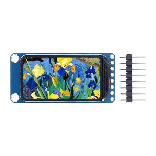 آخر 3 قطع
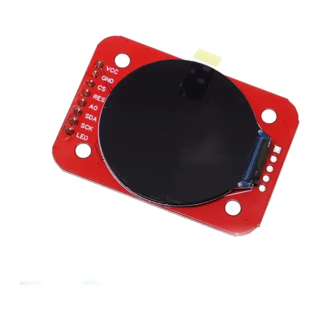 متوفر
متوفر
قطع إلكترونية
شاشة LCD دائرية TFT SPI مقاس 1.28 بوصة - RGB 240×240 مع فتحة microSD
★★★★★
(0)
350
ج.م
100
ج.م
متوفر - يوصلك خلال 72 ساعة