
قطع إلكترونية
اسألنا - نرد عليك على واتساب
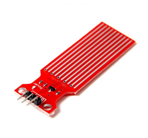
سنسور كشف المطر ومستوى المياه
☆☆☆☆☆
0.0
(مفيش تقييمات)
رمز المنتج: 30745
25
ج.م
متوفر
الكمية:
يوصلك خلال 72 ساعة
دفع آمن. نقبل:
بطاقة بنكية
محفظة إلكترونية
الدفع عند الاستلام
إنستا باي
يُشترى معاً عادةً
 هذا المنتج
سنسور كشف المطر ومستوى المياه
25
ج.م
الإجمالي
39
ج.م
عن هذا المنتج
How Water Level Sensor Works and Interface it with Arduino
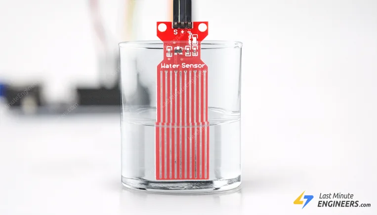
If you have ever had a water heater explode or ever tried to make submersible electronics, then you know how important it is to detect when water is around.
With this Water Level Sensor, you can do just that!
This sensor can be used to measure the water level, monitor a sump pit, detect rainfall or detect leakage.
Hardware Overview
The sensor has a series of ten exposed copper traces, five of which are power traces and five are sense traces.
These traces are interlaced so that there is one sense trace between every two power traces.
Usually these traces are not connected but are bridged by water when submerged.
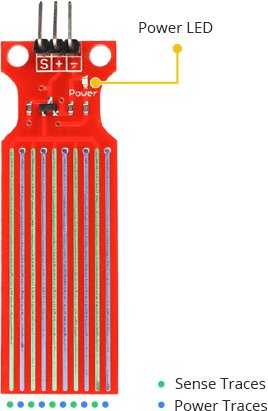
There’s a Power LED on the board which will light up when the board is powered.
How Water Level Sensor Works?
The working of the water level sensor is pretty straightforward.
The series of exposed parallel conductors, together acts as a variable resistor (just like a potentiometer) whose resistance varies according to the water level.
The change in resistance corresponds to the distance from the top of the sensor to the surface of the water.
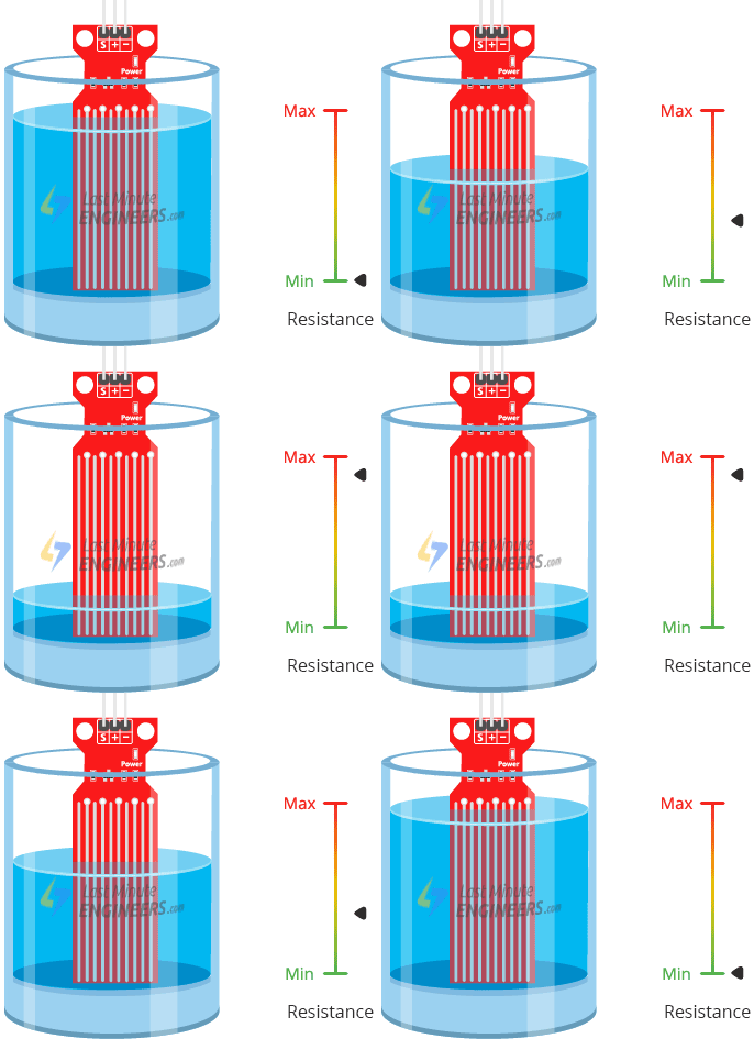
The resistance is inversely proportional to the height of the water:
- The more water the sensor is immersed in, results in better conductivity and will result in a lower resistance.
- The less water the sensor is immersed in, results in poor conductivity and will result in a higher resistance.
The sensor produces an output voltage according to the resistance, which by measuring we can determine the water level.
Water Level Sensor Pinout
The water level sensor is super easy to use and only has 3 pins to connect.
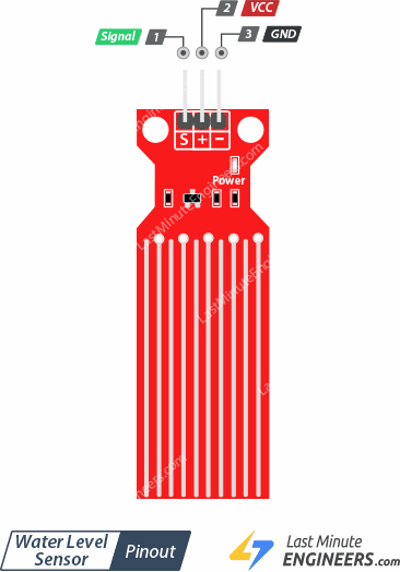
S (Signal) pin is an analog output that will be connected to one of the analog inputs on your Arduino.
+ (VCC) pin supplies power for the sensor. It is recommended to power the sensor with between 3.3V – 5V. Please note that the analog output will vary depending on what voltage is provided for the sensor.
– (GND) is a ground connection.
Wiring Water Level Sensor with Arduino
Let’s hook the water level sensor up to the Arduino.
First you need to supply power to the sensor. For that you can connect the + (VCC) pin on the module to 5V on the Arduino and – (GND) pin to ground.
However, one commonly known issue with these sensors is their short lifespan when exposed to a moist environment. Having power applied to the probe constantly speeds the rate of corrosion significantly.
To overcome this, we recommend that you do not power the sensor constantly, but power it only when you take the readings.
An easy way to accomplish this is to connect the VCC pin to a digital pin of an Arduino and set it to HIGH or LOW as per your requirement. So, we’ll connect the VCC pin to the digital pin #7 of an Arduino.
Finally, connect the S (Signal) pin to the A0 ADC pin on your Arduino.
The following illustration shows the wiring.
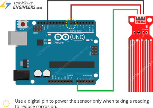
Water Level Sensing Basic Example
Once the circuit is built, upload the following sketch to your Arduino.
// Sensor pins
#define sensorPower 7
#define sensorPin A0
// Value for storing water level
int val = 0;
voidsetup() {
// Set D7 as an OUTPUT
pinMode(sensorPower, OUTPUT);
// Set to LOW so no power flows through the sensor
digitalWrite(sensorPower, LOW);
Serial.begin(9600);
}
voidloop() {
//get the reading from the function below and print it
int level = readSensor();
Serial.print("Water level: ");
Serial.println(level);
delay(1000);
}
//This is a function used to get the reading
intreadSensor() {
digitalWrite(sensorPower, HIGH); // Turn the sensor ON
delay(10); // wait 10 milliseconds
val = analogRead(sensorPin); // Read the analog value form sensor
digitalWrite(sensorPower, LOW); // Turn the sensor OFF
return val; // send current reading
}
Once the sketch is uploaded, open a Serial Monitor window to see the output from the Arduino. You should see a value 0 when the sensor is not touching anything. To see it sense water, you can take a glass of water and slowly put the sensor in it.
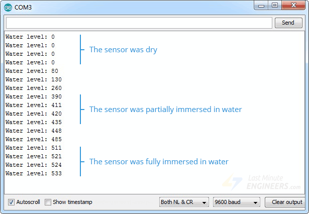
The sensor is not designed to be fully submersed, be careful to install it so that only the exposed traces on the PCB will come in contact with water.
Explanation:
The sketch begins with the declaration of the Arduino pins to which the sensor’s + (VCC) and S (signal) pins are connected.
#define sensorPower 7
#define sensorPin A0
Next, we define a variable val that stores the current water level.
int val = 0;
Now in the Setup section, we first declare the power connection to the sensor as output, then we set it low so no power flows through the sensor initially. We also setup the serial monitor.
pinMode(sensorPower, OUTPUT);
digitalWrite(sensorPower, LOW);
Serial.begin(9600);
In the loop section, we call readSensor() function repeatedly at the interval of one second and print the returned value.
Serial.print("Water level: ");
Serial.println(readSensor());
delay(1000);
The readSensor() function is used to get the current water level. It turns the sensor ON, waits for 10 milliseconds, reads the analog value form sensor, turns the sensor OFF and then returns the analog value.
intreadSensor() {
digitalWrite(sensorPower, HIGH);
delay(10);
val = analogRead(sensorPin);
digitalWrite(sensorPower, LOW);
return val;
}
Calibration
To get accurate readings out of your water level sensor, it is recommended that you first calibrate it for the particular type of water that you plan to monitor.
As you know pure water is not conductive. It’s actually the minerals and impurities in water that makes it conductive. So, your sensor may be more or less sensitive depending on the type of water you use.
Before you start storing data or triggering events, you should see what readings you are actually getting from your sensor.
Using the sketch above, note what values your sensor outputs when the sensor is completely dry -vs- when it is partially submerged in the water -vs- when it is completely submerged.
For example, using the same circuit above, you’ll see the close to the following values in the serial monitor when the senor is dry (0) and when it is partially submerged in the water (~420) and when it is completely submerged (~520).
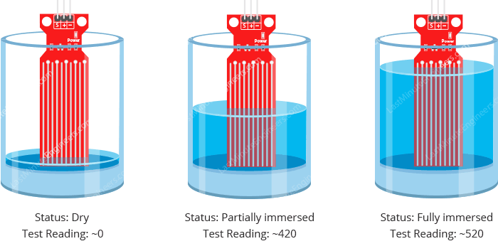
This test may take some trial and error. Once you get a good handle on these readings, you can use them as threshold if you intend to trigger an action. In the next example, we are going to do just that.
Water Level Sensing Project
For our next example, we’re going to make a portable water level sensor that will light up LEDs according to the water level.
Wiring
We’ll use the circuit from the previous example. This time we just need to add some LEDs.
Connect three LEDs to digital pins #2, #3 and #4 through 220Ω current limiting resistors.
Hook up your circuit as pictured below:
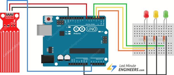
Arduino Code
Once the circuit is built, upload the following sketch to your Arduino.
In this sketch two variables are defined viz. lowerThreshold and upperThreshold. These variables represent our threshold levels.
Anything below the lower threshold will trigger the red LED to turn on. Anything above the upper threshold will turn on the green LED. Anything between these will turn on the yellow LED.
/* Change these values based on your calibration values */
int lowerThreshold = 420;
int upperThreshold = 520;
// Sensor pins
#define sensorPower 7
#define sensorPin A0
// Value for storing water level
int val = 0;
// Declare pins to which LEDs are connected
int redLED = 2;
int yellowLED = 3;
int greenLED = 4;
voidsetup() {
Serial.begin(9600);
pinMode(sensorPower, OUTPUT);
digitalWrite(sensorPower, LOW);
// Set LED pins as an OUTPUT
pinMode(redLED, OUTPUT);
pinMode(yellowLED, OUTPUT);
pinMode(greenLED, OUTPUT);
المواصفات التقنية
لسه مفيش مواصفات مسجلة
بنسجل المواصفات التقنية للمنتج ده وهتظهر هنا أول ما تخلص.
التقييمات
0.0
☆☆☆☆☆
لسه مفيش تقييمات
5★
0
4★
0
3★
0
2★
0
1★
0
لسه مفيش تقييمات للمنتج ده
كن أول واحد يقيّمه وتساعد اللي بعدك يقرر.
الأسئلة الشائعة
لسه مفيش أسئلة على المنتج ده
أول ما توصلنا أسئلة متكررة على المنتج ده هنجاوب عليها هنا.
مش لاقي إجابتك؟
اسألنا - نرد عليك على واتساب
منتجات مرتبطة
قد يعجبك أيضاً
 متاح للطلب
 متوفر
متوفر
 متوفر
متوفر
 متوفر
متوفر
 متاح للطلب
 متوفر
متوفر
 آخر 3 قطع
 متوفر
متوفر
قطع إلكترونية
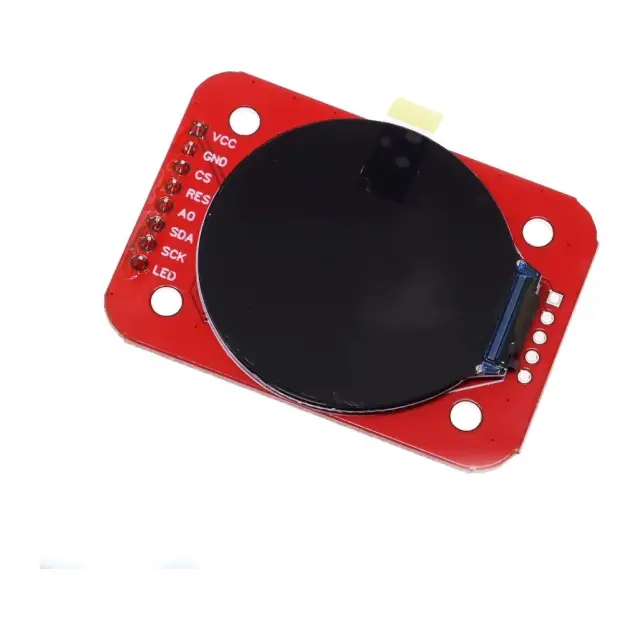
شاشة LCD دائرية TFT SPI مقاس 1.28 بوصة - RGB 240×240 مع فتحة microSD
★★★★★
(0)
350
ج.م
25
ج.م
متوفر - يوصلك خلال 72 ساعة